Table Of Content

A diagram is a partial graphic representation of a system's model. The set of diagrams need not completely cover the model and deleting a diagram does not change the model. The model may also contain documentation that drives the model elements and diagrams (such as written use cases). We use Activity Diagrams to illustrate the flow of control in a system. We can also use an activity diagram to refer to the steps involved in the execution of a use case.
Activity Diagram Example
However, object diagrams depict a system at a specific time—useful for testing different class diagram instances. The Sequence Diagram models the collaboration of objects based on a time sequence. It shows how the objects interact with others in a particular scenario of a use case. With the advanced visual modeling capability, you can create a complex sequence diagram in a few clicks. Besides, some modeling tool such as Visual Paradigm can generate sequence diagram from the flow of events which you have defined in the use case description. With the advanced visual modeling capability, you can create complex sequence diagram in few clicks.
UML Diagram Tool
For example, there are symbols for active classes and interfaces. A class symbol can also be divided to show a class's operations, attributes, and responsibilities. Component Diagram Component diagrams describe the organization of physical software components, including source code, run-time (binary) code, and executables. Get Visual Paradigm Community Edition, a free UML tool that can help you learn UML faster & more effectively.
Types of UML diagrams—and how to read them
A UML diagram serves as a blueprint for a software system and shows how it behaves. To standardize software modeling, UML diagrams use unified modeling language1. This helps developers and other key players describe, design, and document technical details with ease. UML is a way of visualizing a software program using a collection of diagrams. Today, UML is accepted by the Object Management Group (OMG) as the standard for modeling software development.
Visual Paradigm Community Edition supports all UML diagram types. You can link up the "real" diagrams and achieve high degree navigability between diagrams inside the Interaction Overview Diagram. The goal of UML is to provide a standard notation that can be used by all object-oriented methods and to select and integrate the best elements of precursor notations. Hence, it provides constructs for a broad range of systems and activities (e.g., distributed systems, analysis, system design and deployment). Timing Diagram are a special form of Sequence diagrams which are used to depict the behavior of objects over a time frame. We use them to show time and duration constraints which govern changes in states and behavior of objects.
Since behavior diagrams illustrate the behavior of a system, they are used extensively to describe the functionality of software systems. As an example, the activity diagram describes the business and operational step-by-step activities of the components in a system. A class diagram allows you to map the structures of a system displaying various classes, attributes, operations, and relationships between objects. Both software engineers and business managers use this interaction diagram to model different connections involved within a process. Timing Diagram A timing diagram is a type of behavioral or interaction UML diagram that focuses on processes that take place during a specific period of time. They're a special instance of a sequence diagram, except time is shown to increase from left to right instead of top down.
Business process modeling notation (BPMN): Everything you need to know
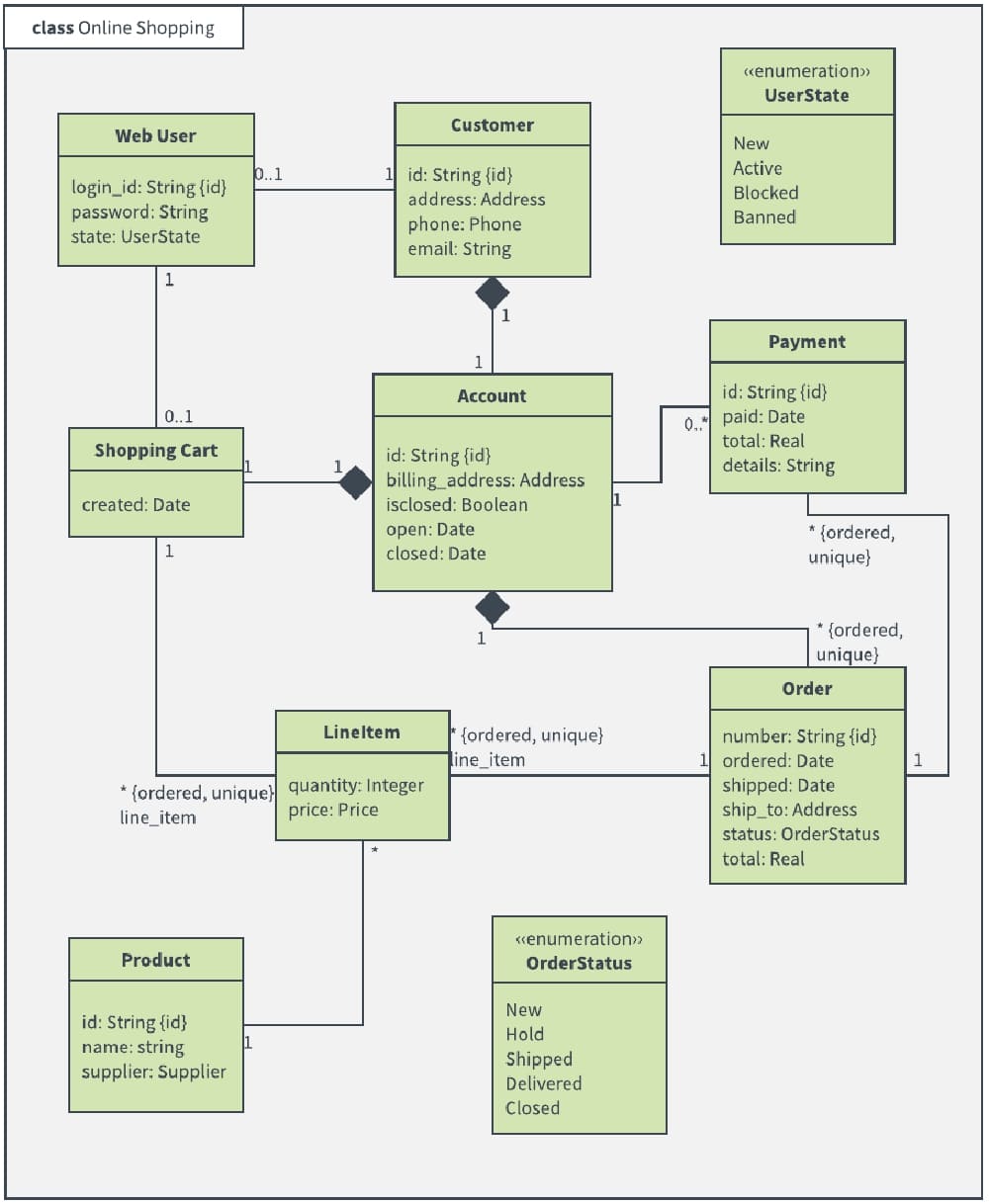
State diagrams depict the permitted states and transitions as well as the events that effect these transitions. It helps to visualize the entire lifecycle of objects and thus help to provide a better understanding of state-based systems. For example, in an online banking system you may create classes like 'User', 'Account', 'Transaction', etc. In a classroom management system you may create classes like 'Teacher', 'Student', 'Assignment', etc. In each class, there are attributes and operations that represent the characteristic and behavior of the class. Class Diagram is a UML diagram where you can visualize those classes, along with their attributes, operations and the inter-relationship.
Use these diagrams to show how the parts of a system connect to make a system run. For a bank ATM system, those parts might include a central processor, card reader, memory, and modem. Organize components and subcomponents in an object-oriented system, and record how these components interface with each other. In an email app, components might include email management, inbox, and outbox.
For example, your timing diagram for web browsing might display various states—waiting, processing, idling—and how long each state takes when a user browses a website. Behavioral diagrams model interactions in a system’s dynamic sequence or flow. Group high-level system elements into (yep) packages, or folders, to show their hierarchy, relationships, and dependencies.

In this kind of relationship, the child class can exist independently of its parent class. UML helps software engineers describe and visualize a system, no matter what language it’s coded in. Use Lucidchart to collaborate on UML diagrams in real time with your team. When you’re ready, present your work from Lucidchart or share it in popular apps like Confluence and Jira. This is a diagram type that is very rarely used in any specification. For more profile diagram templates, visit our diagram community.
Customizable features could be anything from adding text and shapes to creating new tables and even designing custom templates. Just make sure that you know what features you need before you start looking, and you can keep an eye out for something that fits the bill. Collaborative features allow you to work together with team members in one location. This makes it easier for everyone in your team to work on the same UML diagram, provide feedback, and use the diagram when it’s been approved. There’s a lot of software out there to choose from, which can be pretty overwhelming if you’re new to UML diagrams.
There are two main categories; structure diagrams and behavioral diagrams. Click on the links to learn more about a specific diagram type. Class diagrams represent the static structures of a system, including its classes, attributes, operations, and objects. A class diagram can display computational data or organizational data in the form of implementation classes and logical classes, respectively.
Once each item is allocated to a package, all of the packages are then arranged and ranked hierarchically in the diagram. A component diagram breaks down a complex system into smaller components, making it easier to visualize. Unlike other UML diagrams, it specifically outlines the relationship between these components. Similar to the Sequence Diagram, the Communication Diagram is also used to model the dynamic behavior of the use case. When compared to the Sequence Diagram, the Communication Diagram is more focused on showing the collaboration of objects rather than the time sequence.
They are actually semantically equivalent, so some of the modeling tool such as, Visual Paradigm allows you to generate it from one to the other. Package diagram is UML structure diagram which shows packages and dependencies between the packages. Model diagrams allow to show different views of a system, for example, as multi-layered (aka multi-tiered) application - multi-layered application model. UML Object Diagram shows how object instances in your system are interacting with each other at a particular state.
Electronics Lab to Train Students in Printed Circuit Board Manufacturing - UMass Lowell
Electronics Lab to Train Students in Printed Circuit Board Manufacturing.
Posted: Fri, 02 Feb 2024 08:00:00 GMT [source]
Use these diagrams for medium- to large-scale layered apps, such as an omnichannel shopping platform. Structural diagrams represent technical frameworks, detailing static components in a structure or system. Deployment diagrams are consist of nodes and their relationships. An efficient deployment diagram is an integral part of software application development. The first thing to notice about the UML is that there are a lot of different diagrams (models) to get used to.


No comments:
Post a Comment